A bicycle
can be self-stable without gyroscopic or caster effects,
Science 15 April 2011:
332(6027),
339-342. [doi:10.1126/science.1201959]
J. D. G. Kooijman, Delft University of Technology, jodikooijman@gmail.com
J. P. Meijaard, University of Twente, j.p.meijaard@ctw.utwente.nl
Jim M. Papadopoulos, University of Wisconsin-Stout, papadopoulos@alum.mit.edu
Andy Ruina, Cornell University, ruina@cornell.edu
A. L. Schwab, Delft University of Technology, a.l.schwab@tudelft.nl
The paper and supporting material
1) Preprint: 4 page pdf
2) Supporting text: 50 page pdf
3) Simultaneously posted history paper: http://hdl.handle.net/1813/22497 (40 page pdf)
History of thoughts about bicycle self-stability
J. P. Meijaard, Jim M. Papadopoulos, Andy Ruina, and A. L. Schwab
Background
Long known, but still amazing, is that a moving bicycle can
balance itself (see
videos). Most
people think this balance follows from a gyroscopic effect.
That's what Felix Klein
(of the Klein bottle),
Arnold
Sommerfeld (nominated for
the Nobel prize 81 times) and
Fritz
Noether (Emmy's
brother) thought
[1]. On the
other hand a famous paper by David Jones [2] (published
twice in Physics Today) claims bicycle stability is also
because of something
called "trail". Trail is the distance the front wheel
trails behind the
steer axis. The front wheel of a shopping cart castor trails
behind its support
bearing and so must a bicycle front wheel, Jones reasoned. Jones
insisted that
trail was a necessary part of bicycle stability.
We suspected that such simple images (above) were missing at
least part of the
picture.
To find the essence of bicycle self balance we looked at simpler
and simpler
dynamical models until we found a minimal two-mass-skate (TMS)
bicycle that
theory told us should be self-stable. This bicycle has no
gyroscopic effect and
no trail. We built a bicycle (of sorts) based on the theory to
prove the point.
This bicycle proves that self-stability cannot be explained in
any simple words.
Bicycles are not stable because of gyros, because you can make a
self stable
bicycle without gyros. We did that. And they are not stable
because of trail,
you can take that away too. And we did that. More positively, we
have shown that
the distribution of mass, especially the location of the center
of mass of the
front assembly, has as strong an influence on bicycle stability
as do gyros and
trail.
Why can a bicycle balance itself? One necessary condition for
bicycle self
stability is (once we define the words carefully) that such a
bicycle turns into
a fall.
The paper and supplementary material describe the problem and
our solution in
more detail.
This research was started by Jim Papadopoulos, working with Andy
Ruina and Scott
Hand at Cornell in 1985. The basic theoretical result was
in-hand then. In some
sense, the recent Proceedings of the Royal Society paper on
bicycle stability [3]
was written to support the present paper. We couldn't publish
this gyro-free-no-trail result without that foundation being in
the literature. The experimental two-mass-skate (TMS) bicycle,
and the fleshing out of the theory, were carried out by Jodi
Kooijman and Arend Schwab at Delft University of Technology,
starting in
2008. Jaap Meijaard found the key errors in Klein &
Sommerfeld
[1] and in Whipple [4].
 |
Here is a
video of Arend Schwab narrating the text above: |
 |
Here is a
video of Andy Ruina explaining how bicycles balance: |
References:
[1] F. Klein and A. Sommerfeld.
Über die Theorie des Kreisels.
Teubner, Leipzig,
1910. Ch IX §8, Stabilität
des Fahrrads, by F. Noether, pp. 863–884.
(pdf+English
translation).
[2] D. E. H. Jones. The
stability of the bicycle. Physics Today, 23(4):34–40,
1970.
DOI:10.10631/1.3022064
(2006 DOI:10.1063/1.2364246)
[3] J. P. Meijaard, Jim M.
Papadopoulos, Andy Ruina, and A. L. Schwab. Linearized
dynamics equations for
the balance and steer of a bicycle: a benchmark and review. Proceedings
of
the Royal Society A, 463:1955–1982, 2007. DOI:10.1098/rspa.2007.1857
(pdf)
[4] F. J. W. Whipple. The stability of the
motion of a bicycle. Quart. J. Pure Appl. Math.
30:312–348, 1899.
Links:
Yellow Bicycle stability demonstration photos and videos:
http://bicycle.tudelft.nl/yellowbicycle/
Andy Ruina's Bicycle
Mechanics and Dynamics webpage:
http://ruina.tam.cornell.edu/research/topics/bicycle_mechanics/overview.php
Arend L. Schwab's Bicycle
Mechanics and Dynamics:
http://bicycle.tudelft.nl/schwab/Bicycle/index.htm
VIDEOS:
 |
Video 1,
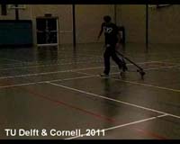
basic experiment: (also on Science website) full size: 1201959Video1BasicExperiment.mov (9.8MB) low res: 1201959Video1BasicExperiment.mp4 (1.2MB) or on Youtube. This video shows two typical experimental runs, both at stable forward speed. The first run shows stable straight ahead motion, and the second run shows laterally perturbed stable motions. |
 |
Video
2, counter-spinning wheels: (also on Science
website) full size: 1201959Video2CounterSpinningWheels.mov (4.7MB) low res: 1201959Video2CounterSpinningWheels.mp4 (0.6MB) or on Youtube. This video demonstrates the working of the front counter-spinning wheel which eliminates the spin angular momentum of the front wheel. |
 |
Video 3,
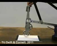
measuring trail: (also on Science website) full size: 1201959Video3MeasuringTrail.mov (22.3MB) low res: 1201959Video3MeasuringTrail.mp4 (2.9MB) or on Youtube. This video shows how we measured the small negative trail (caster) on the experimental two-mass-skate (TMS) bicycle. A piece of paper is placed underneath the front wheel and stuck to the ground with tape. The front wheel is lowered and now touches the paper whereas the rear frame of the bicycle is clamped to prevent it from moving. The handlebars are then turned either way a number of times, marking the paper. The bicycle is removed from the clamp and the mark on the paper is examined. The mark follows an arc, a line is drawn tangentially to either end of the mark. The point where the two lines cross indicates the point about which the wheel rotates. Next the line for the middle of the contact point is drawn on the paper. The distance from the centre point to the arc is the trail. When we measured the trail this way it turned out to be -4 mm, that is center of the contact region was 4 mm ahead of the intersection of the steer axis with the ground. |
 |
Video 4, slow
motion: (also on Science website) full size: 1201959Video4SlowMotion.mov (26.9MB) low res: 1201959Video4SlowMotion.mp4 (3.4MB) or on Youtube. This is a high speed video (300 fps) of one of the experiments where we measured the lateral motions with a wireless inertial sensor (Philips Pi-Node) and forward speed by post-facto counting frames. |
 |
High Def
Composite
(very large file): 1201959_HD_StableBicycleTeaser.mov (0.4GB) (1920x1080) or on Youtube. This HD video gives an overview of the two-mass-skate (TMS) bicycle and it's stable motions. |
 |
High Def
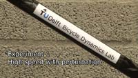
Experiments 1 High Speed Perturbed Stable (very large
file): 1201959_HD_StableBicycleExp1.mov (1.2GB) (1920x1080) or on Youtube. This HD video shows that the two-mass-skate (TMS) bicycle is stable at high speed, even when laterally perturbed. |
 |
High Def
Experiments 2 High Speed Stable (very large file): 1201959_HD_StableBicycleExp2.mov (0.7GB) (1920x1080) or on Youtube. This HD video shows that the two-mass-skate (TMS) bicycle is stable at high speed. |
 |
First Successful Run: GB7sv7firstrun.MOV (1.7MB) or on Youtube. The video shows the first successful run with the experimental primitive bicycle after replacing the polyurethane “inline skate” wheels with sharp edge aluminum wheels, with a crown radius of 2 mm. |
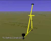 |
Simulation: GB7S4v2fv300.MOV (1.5MB) or on Youtube. The video shows an animation (VRML) of a simulation of the full nonlinear model with with the multibody dynamics software SPACAR. This to check if the system still behaves stably as predicted by the linearized analysis. The initial forward speed is 3 m/s, then after 1 sec the bicycle is laterally perturbed with an initial leanrate of 0.6 rad/s. The transient dies out and the bicycle comes back up again; stable indeed! |
HIGH RES ILLUSTRATIONS:
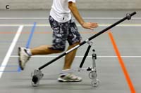 |
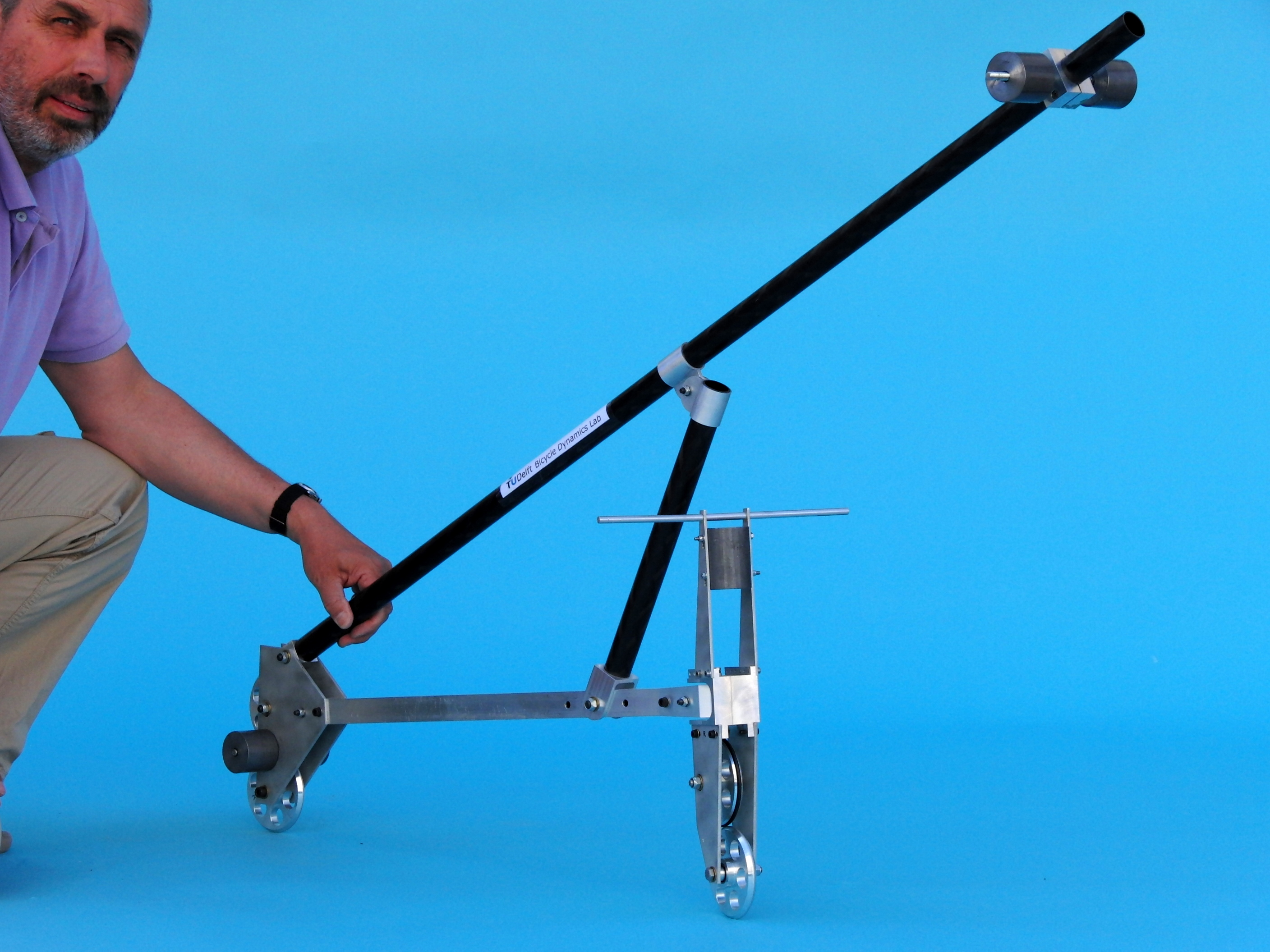
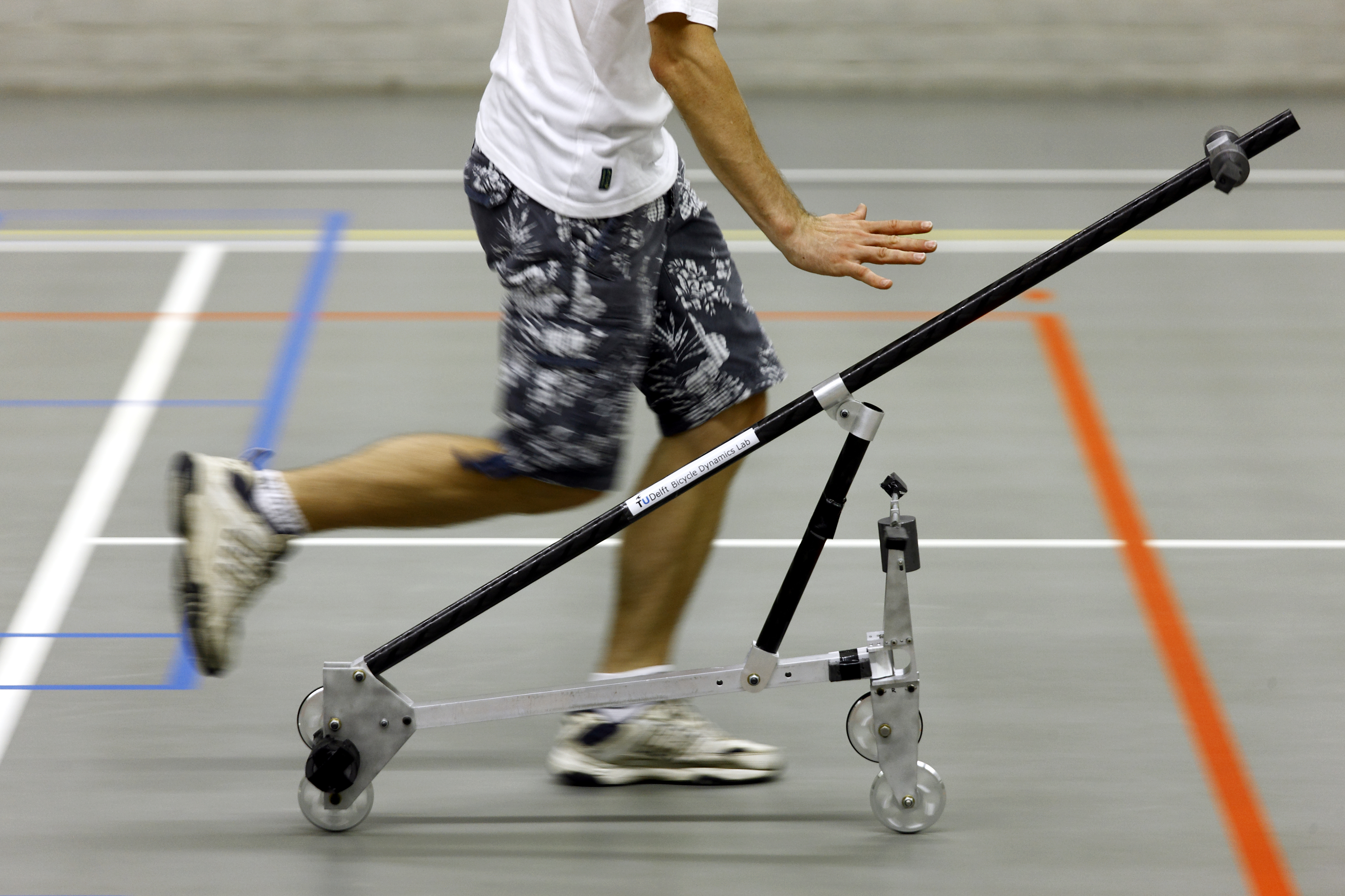
Fig 2C from the paper: fig2cStableBicycleExperiment.pdf (119KB) Original photo: fig2cStableBicycleExperimentLarge.jpg (4.9MB) Self-stable experimental TMS bicycle rolling and balancing (photo by Sam Rentmeester/FMAX). |
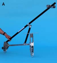 |
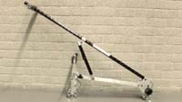
Fig 2A from the paper: fig2aPhysicalStableBicycle.pdf (324KB) Original photo: CIMG0603.JPG (1.6MB) The experimental two-mass-skate (TMS) bicycle. |
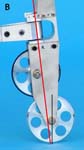 |
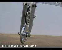
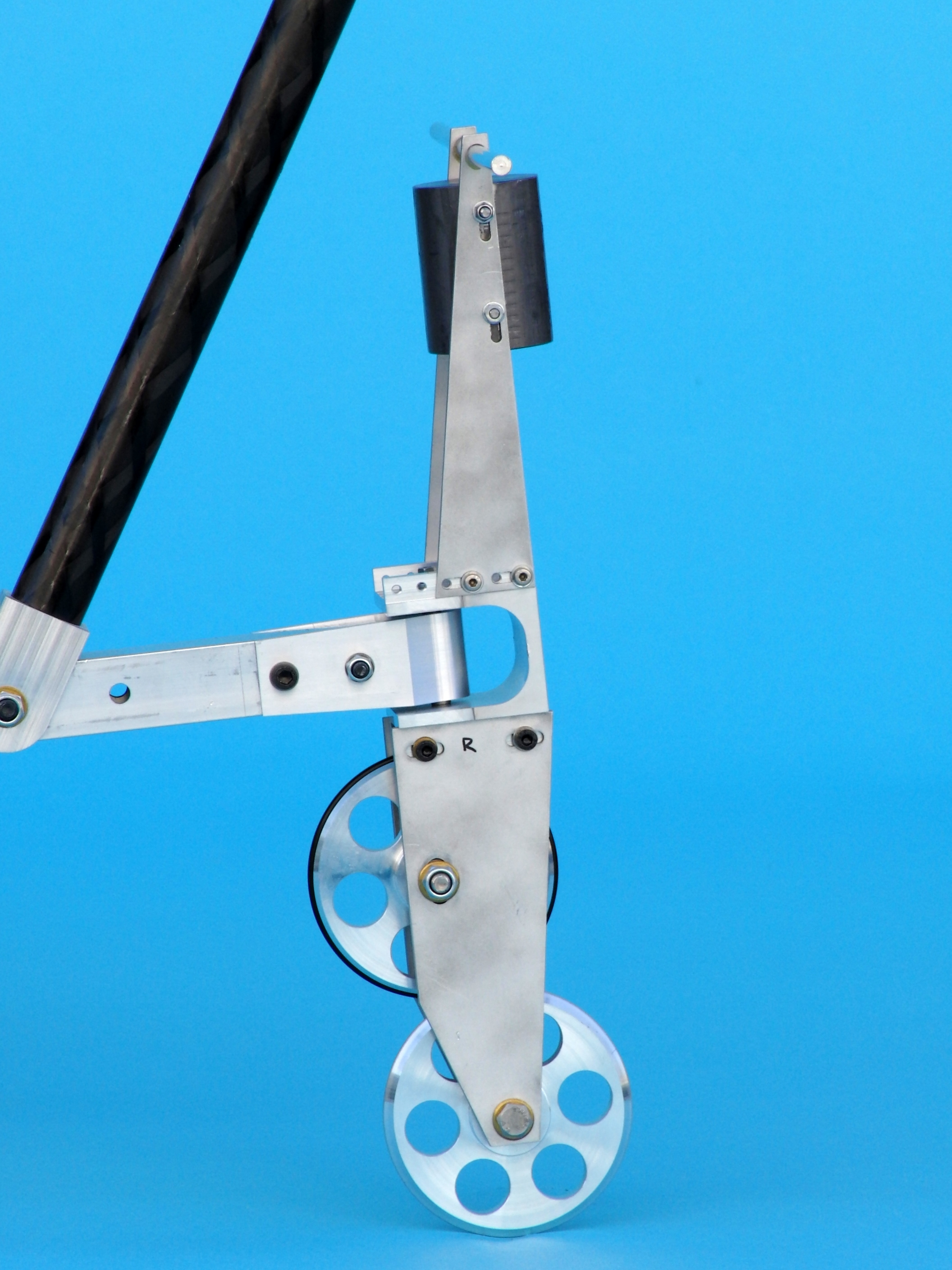
Fig 2B from the paper: fig2bFrontAssembly.pdf (544KB) Original photo: CIMG0592.JPG (1.7MB) Front assembly of the experimental two-mass-skate (TMS) bicycle. A counter-rotating wheel cancels the spin angular momentum. The lines show a small negative trail. |
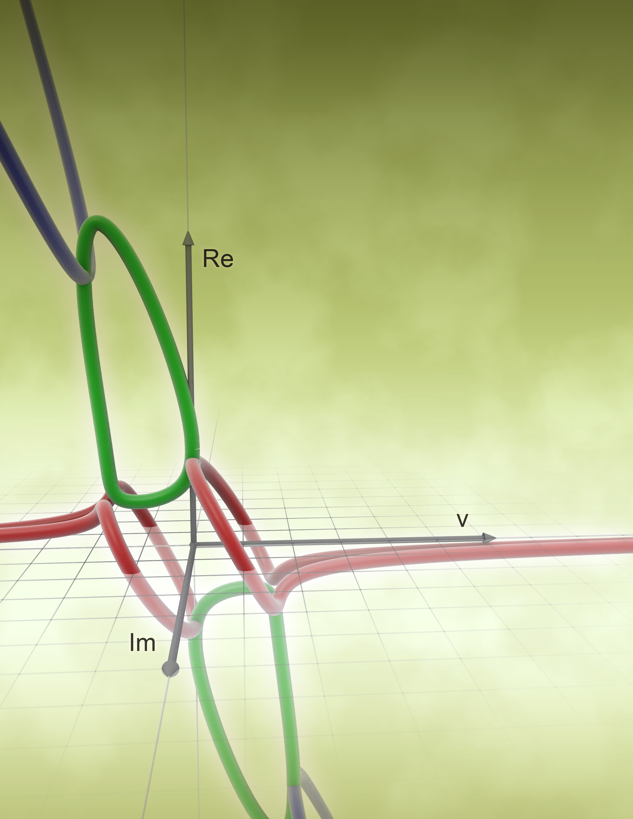 |
Eigentubes: eigentubes7p1.jpg (647KB) (2550x3300) 3D plot of eigenvalues of the theoretical two-mass-skate (TMS) bicycle as a function of speed. Forward speed v is shown on the horizontal x-axis. The vertical axis shows the real part of the eigenvalues. The axis pointing out of the page shows the imaginary part. For speeds where all of the real parts are below the horizontal axis (have negative real part) the TMS bicycle is theoretically stable. This is the rightmost 2/3 of the plot. Negative v corresponds to the bicycle going backwards, which is totally unstable for this bicycle. Rotating the figure 180 degrees about the Im axis reproduces the figure because of the reversibility of the equations of motion (illustration by Peter de Lange). |
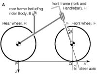 |
Fig 1A from the paper: fig1aBicycleModel.pdf (30KB) The bicycle model consists of two frames B and H connected by two wheels R and F. The model has a total of 25 geometry and mass-distribution parameters. Central here are the rotary inertia Iyy of the front wheel, the steer axis angle (‘rake’) ls and the trail distance c (positive if contact is behind the steer axis). Depending on the parameter values, as well as gravity g and forward speed v, this bicycle can be self-stable or not. |
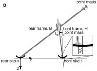 |
Fig 1B from the paper: fig1bStableBicycleModel.pdf (27KB) A two-mass-skate (TMS) bicycle is a special case. It is described with only 9 free parameters (8 + trail). The wheels have no inertia and are thus effectively ice-skates. The two frames each have a single point mass and no mass moments of inertia. A heavy point mass at the rear skate at the ground contact point can prevent the bicycle from tipping over frontward; because it has no effect on the linearized dynamics it is not shown. Even with negative trail (c < 0, see inset) this non-gyroscopic bicycle can be self-stable. |
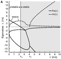 |
Fig 3A from the paper: fig3aEigenvaluesStableBicycle.pdf (29KB) Stability plot for the experimental TMS stable bicycle. Solutions of the differential equations are exponential functions of time. Stability corresponds to all such solutions having exponential decay (rather than exponential growth). Such decay only occurs if all four of the eigenvalues li (which are generally complex numbers) have negative real parts. The plot shows calculated eigenvalues as a function of forward speed v. For v > 2.3m/s (the shaded region) the real parts (solid lines) of all eigenvalues are negative (below the horizontal axis) and the bicycle is self-stable. |
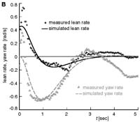 |
Fig 3B from the paper: fig3bLeanYawRateStableBicycle.pdf (33KB) Transient motion after a disturbance for the experimental TMS bicycle. Measured and predicted lean and yaw (heading) rates of the rear frame are shown. The predicted motions show the theoretical (oscillatory) exponential decay. Not visible in these plots, but visible in high-speed video (Video 4), is a 20 Hz shimmy that is not predicted by the low-dimensional linearized model. |
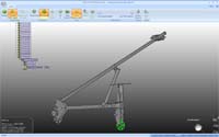 |
CAD
model: The CAD model of the experimental two-mass-skate (TMS) bicycle is available in three formats: - SolidWorks GB7Sv9cSolidworksModel.zip (6.7MB) - pdf's of all parts GB7Sv9cProductionDrawings.zip (244KB) - STEP file GB7Sv9cSTEPModel.STEP (2.3MB) |
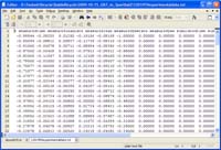 |
Experimental data: The experimental data together with the estimated simulated data which is presented in Fig 3B from the paper, is here presented in this plain ascii text file: 1201959experimentaldata.txt (16KB) The first two lines is a header which explains the contents of each column. |
| Thesis
Jodi Kooijman: J.D.G.Kooijman, "Bicycle rider control; observations, modelling & experiments", PhD thesis, Delft University of Technology, 18 sep 2012 (pdf 53.7Mb) |
- Any
questions or
comments? Please contact
Arend
L. Schwab
-